Over the weekend, I visited my other location and set a Meraki Z4 up. This also allowed me an opportunity to configure a Site-to-Site IPsec VPN tunnel between this location and my main location that’s running a pfSense appliance. This tunnel will be used for off-site backup transfers.
The process of setting up the site-to-site IPsec tunnel is fairly straightforward. I think it took me five times as long to write this post than to actually get it running. We’re going to start with the Meraki side and then will shift gears to pfSense. There will be information that we need to share between the two devices during the set up. So, let’s get going.
Meraki
First, go to your Meraki Dashboard network and click Security Appliance (or, in my case, Teleworker gateway) -> Configure -> Site-to-site VPN.
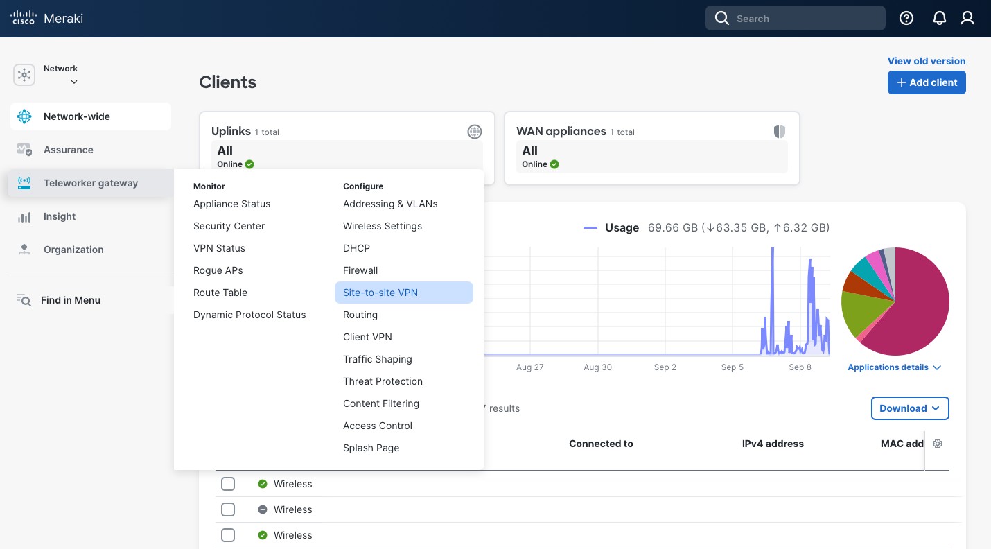
There, scroll about half way, and, under the “IPsec VPN peers” section, click “+ Add a peer”.
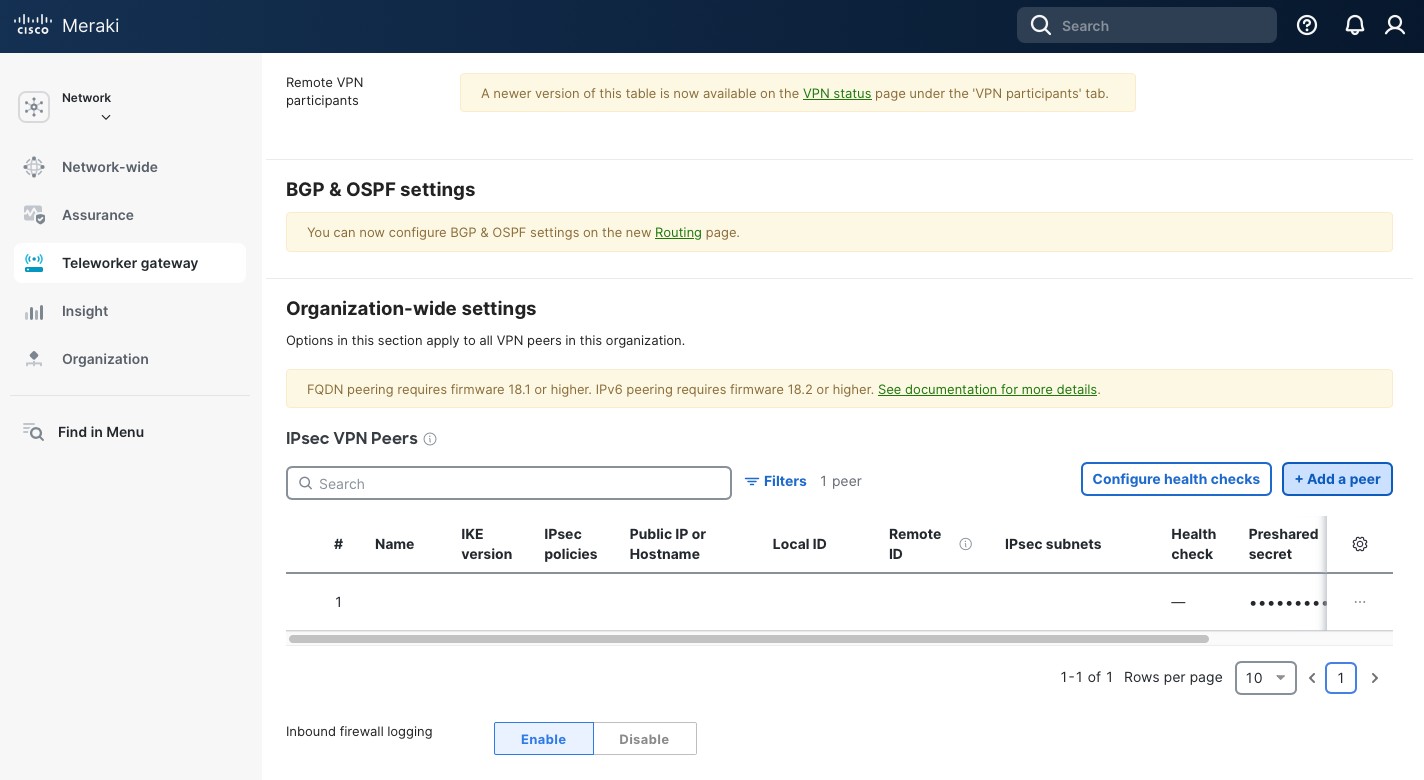
In the new opened pane:
- Type in a “Name”. This name will be used to identify the peer, so choose the name that would make sense to you.
- Select “IKE version” IKEv2 (it allows a bit more options compared to IKEv1).
- In the “Public IP or Hostname” use the IP or the hostname of your remote site. In my case, I am using the fully qualified domain name of my pfSense site. Note, that FQDN peering requires MX (or Z) appliance firmware of 18.1 or higher.
- Type in a “Local ID”. I prefer to use a private IP that is not used in my environment.
- Type in a “Remote ID”. I use the same approach as with the Local ID.
- Next, type in “Shared secret”. This secret will also be used on our pfSense appliance, so make sure you copy it somewhere. Use a strong randomly generated key. You won’t need to type it in so the more complex the better.
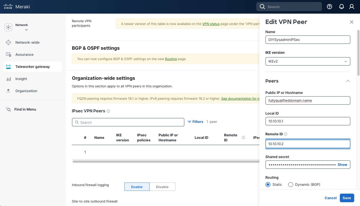
Scrolling down, select:
- “Static” under “Routing”.
- In the “Private subnets”, include the subnets the remote peer (pfSense, in my case) will be advertising to this location.
- “Availability” – select the network this IPsec peer should be peering with.
- Select options for “Tunnel monitoring”. I am not using anything at the moment, but it does require a Health check option to be set up.
- Keep “Failover directly to internet disabled”. We’re only tunneling local subnets so this option is irrelevant to us.
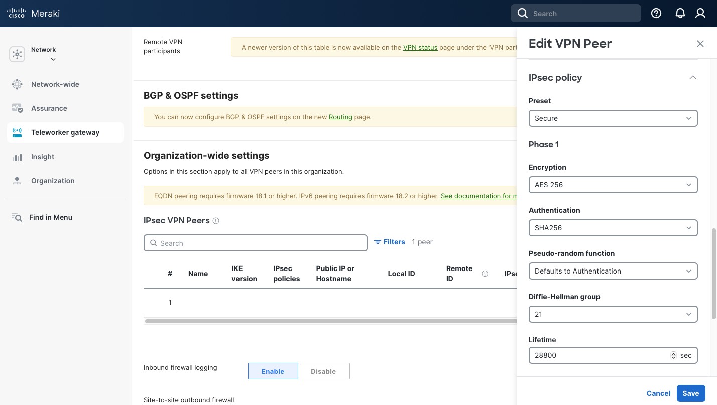
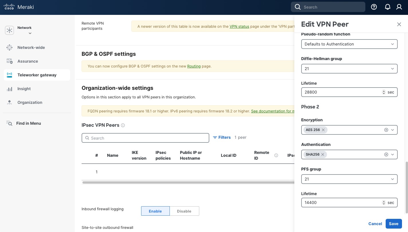
Now, in the “IPsec policy”, select “Preset” “Secure”. It has the highest settings that the Meraki security appliance currently supports and it makes setup easier. The settings for Phase 1 and Phase 2 are below. Take a note, as we’ll need to use the same setting on our remote pfSense peer. When done click “Save” and then “Save Changes” button at the bottom of the page.
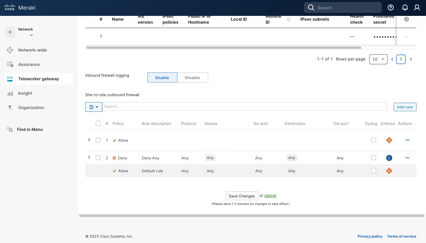
At the bottom of the Site-to-site VPN page you can set the Site-to-site outbound firewall rules. These rules apply to traffic going across the IPsec tunnel. By default, Meraki uses Allow Any. I prefer to allow only what I need and also Deny Any right above the Allow Any “Default rule”.
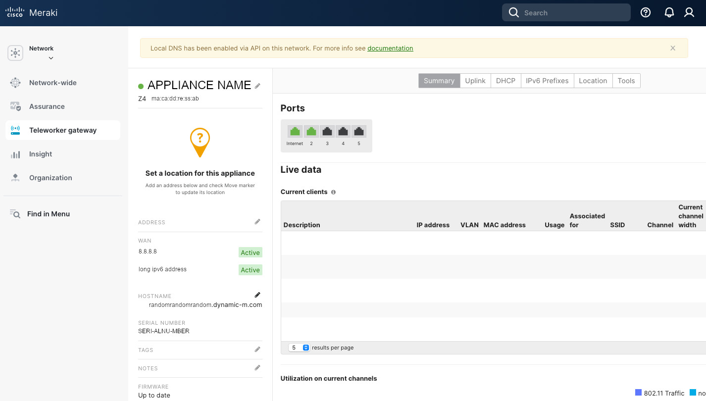
We’re pretty much done with the Meraki side. But, since this tunnel is between two residential locations, we have a dynamic public DNS. Previously, I described how I manage the dynamic public IPs with DynDNS. Meraki makes it super easy as it manages the DynDNS records by default. Go to Security appliance (Teleworker gateway) -> Appliance status. There copy the “Hostname” (ending with .dynamic-m[.]com). We’ll use it when we set up pfSense.
pfSense
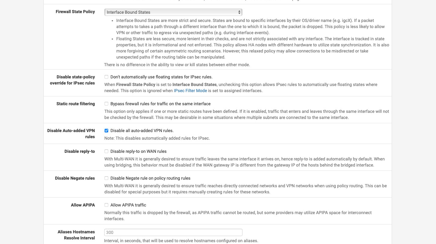
By default, Meraki denies any incoming traffic. When you create an IPsec tunnel, it allows it through the firewall automatically. pfSense does the same. I’m not a dan of it as I’d like more control over my firewall rules. So the first thing we’ll do is go to System -> Advanced -> Firewall & NAT. About half way through you’ll see the “Advanced Options” section. In this section check “Disable all auto-added VPN rule” and click “Save” at the very bottom of the page.
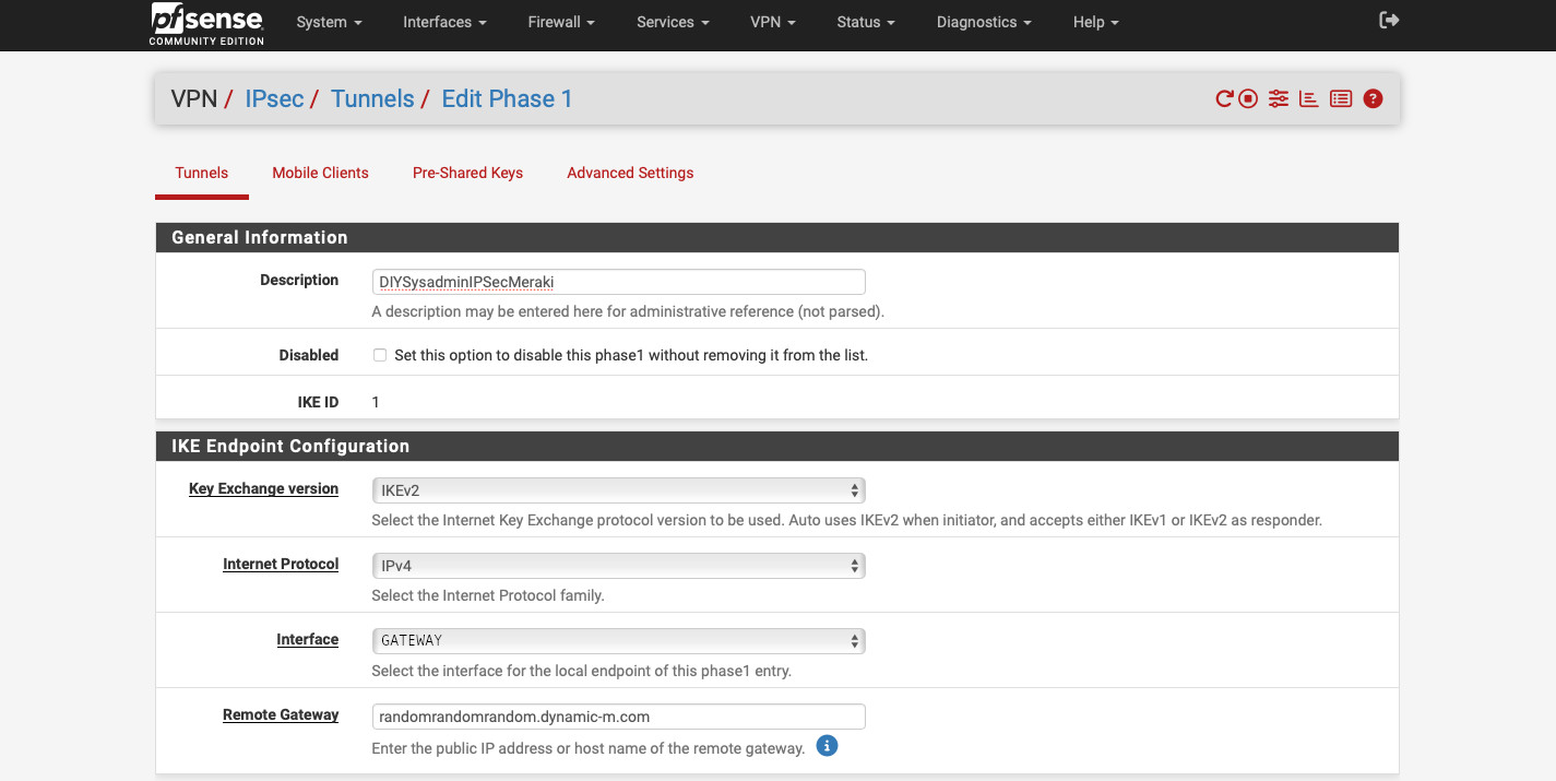
Now go to VPN -> IPsec. There click the “+ Add P1” green button. There:
- Enter the “Description”. This is only for administrative purposes so choose something that would make sense to you.
- Select “Key Exchange version” “IKEv2”.
- In “Interface”, select the interface that is connected to the internet. It is “GATEWAY” in my example.
- In the “Remote Gateway” type in the fully qualified domain name for your Meraki appliance. We copied it from the Appliance status page, it ends with .dynamic-m[.]com.
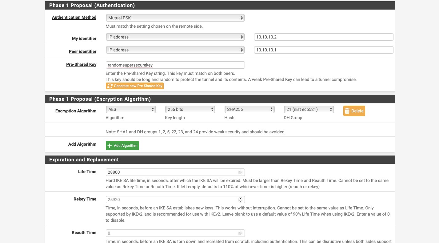
- For the “Phase 1 Proposal (Authentication)” select “Mutual PSK” for the “Authentication Method”.
- For “My identifier” and “Peer identifier” use the same IP addresses you used on the Meraki side (the Meraki identifier is the “Peer identifier” in this case).
- Paste the super secret and complex key you used on the Meraki appliance into the “Pre-Shared Key” field.
- For the “Phase 1 Proposal (Encryption Algorithm), we need to use the same settings as on our Meraki appliance.
- Use “AES” for “Algorithm”.
- Use “256 bits” for “Key length”.
- Use “SHA256” for “Hash”.
- Use “21 (nist ecp521)” for “DH group”.
- Select “Life Time” of “28800”.
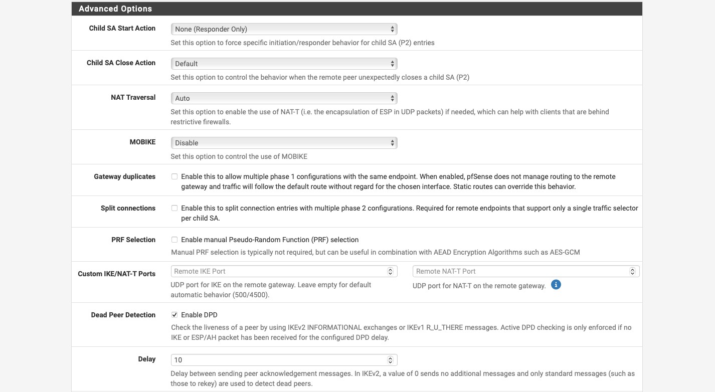
In the “Advanced Options” select “None (Responder Only)” for “Child SA Start Action”. This forces the Meraki device to initiate the tunnel. You can leave everything else at default. Click the blue “
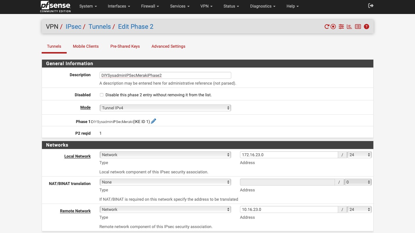
Now, in the “VPN / IPsec / Tunnels” expand the item we’ve just created by clicking on the “Show Phase 2 Entries” button and then click the green “+ Add P2” button. There:
- Enter a description.
- Select “Tunnel IPv4” for the “Mode”. This is the mode we’ll use for the static routing through our IPsec tunnel.
- Under “Networks” subsection, for “Local Network” select “Network” for the “Type” and enter the IP sunset that the pfSense appliance will be sharing through the tunnel.
- Do the same thing for the “Remote Network” but enter the IP subnet that the Meraki device will be sharing.
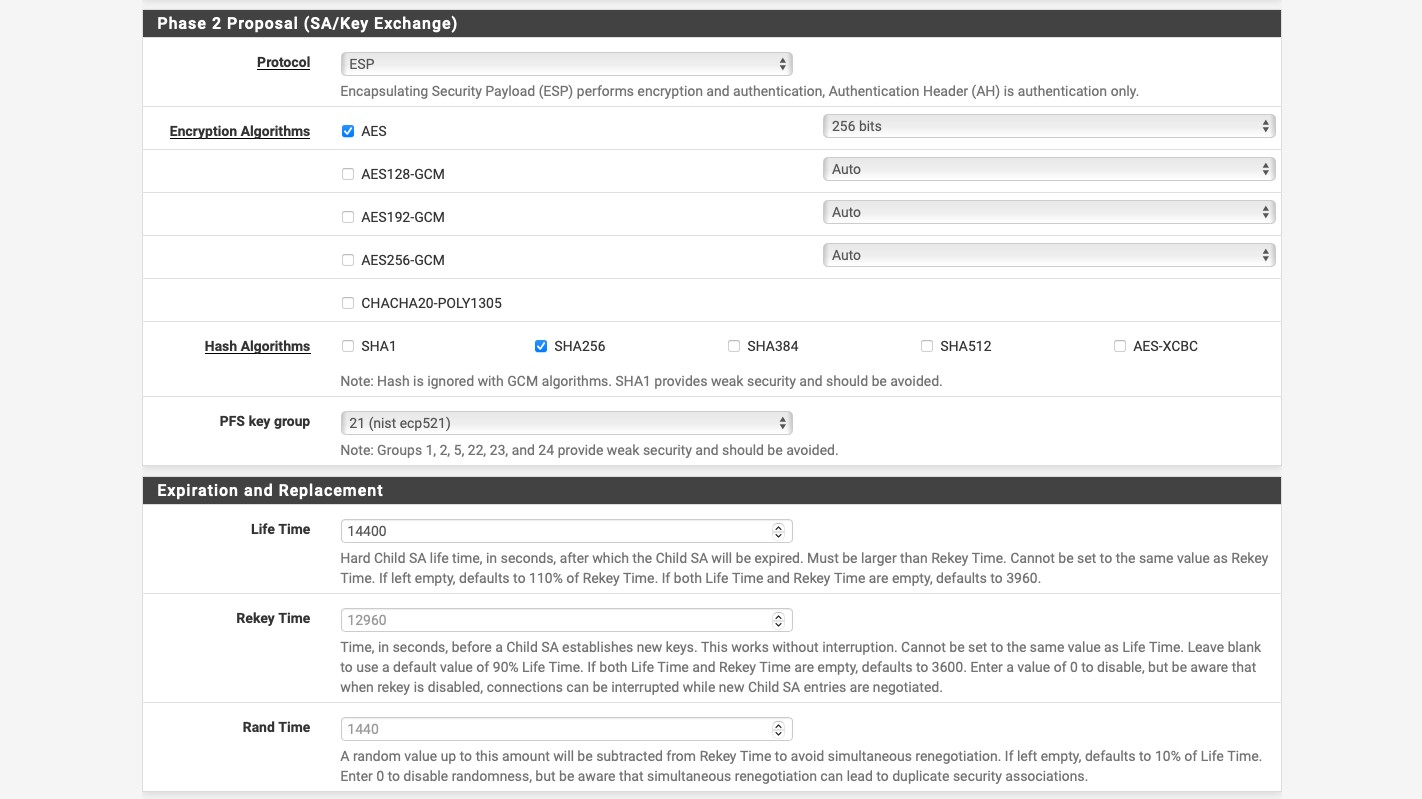
In the “Phase 2 Proposal (SA/Key Exchange)”, enter:
- “ESP” for “Protocol”. This is what enables encryption of the IPsec tunnel.
- “AES” and “256 bits” for “Encryption Algorithms”.
- “SHA256” for “Hash Algorithms”.
- “21 (nist ecp521)” for “PFS key group”.
- Under the “Expiration and Replacement” select “14400” for “Life Time”. And then click the blue “Save” button.
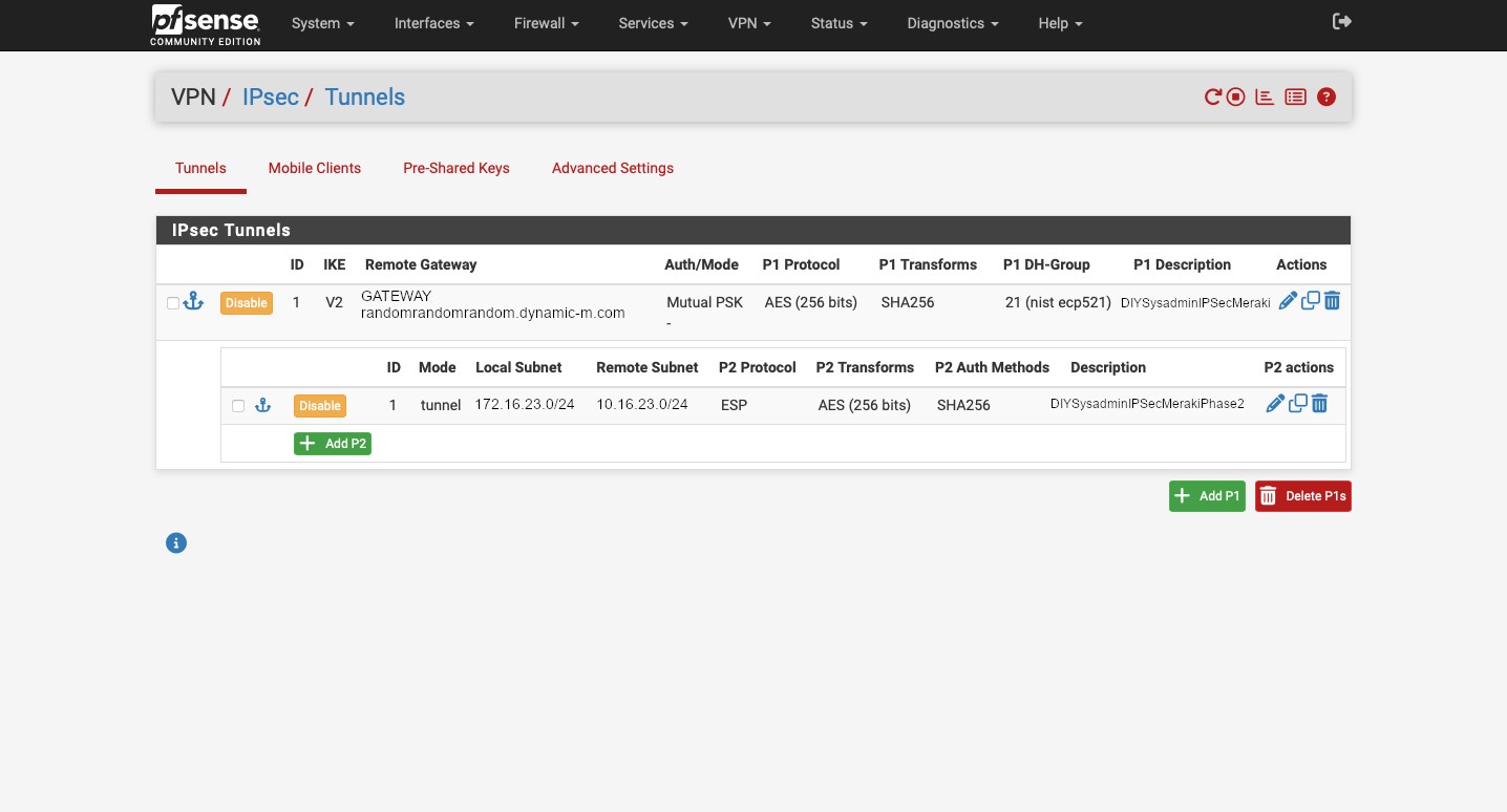
OK. We’re done with the tunnel set up. It should look something like this:
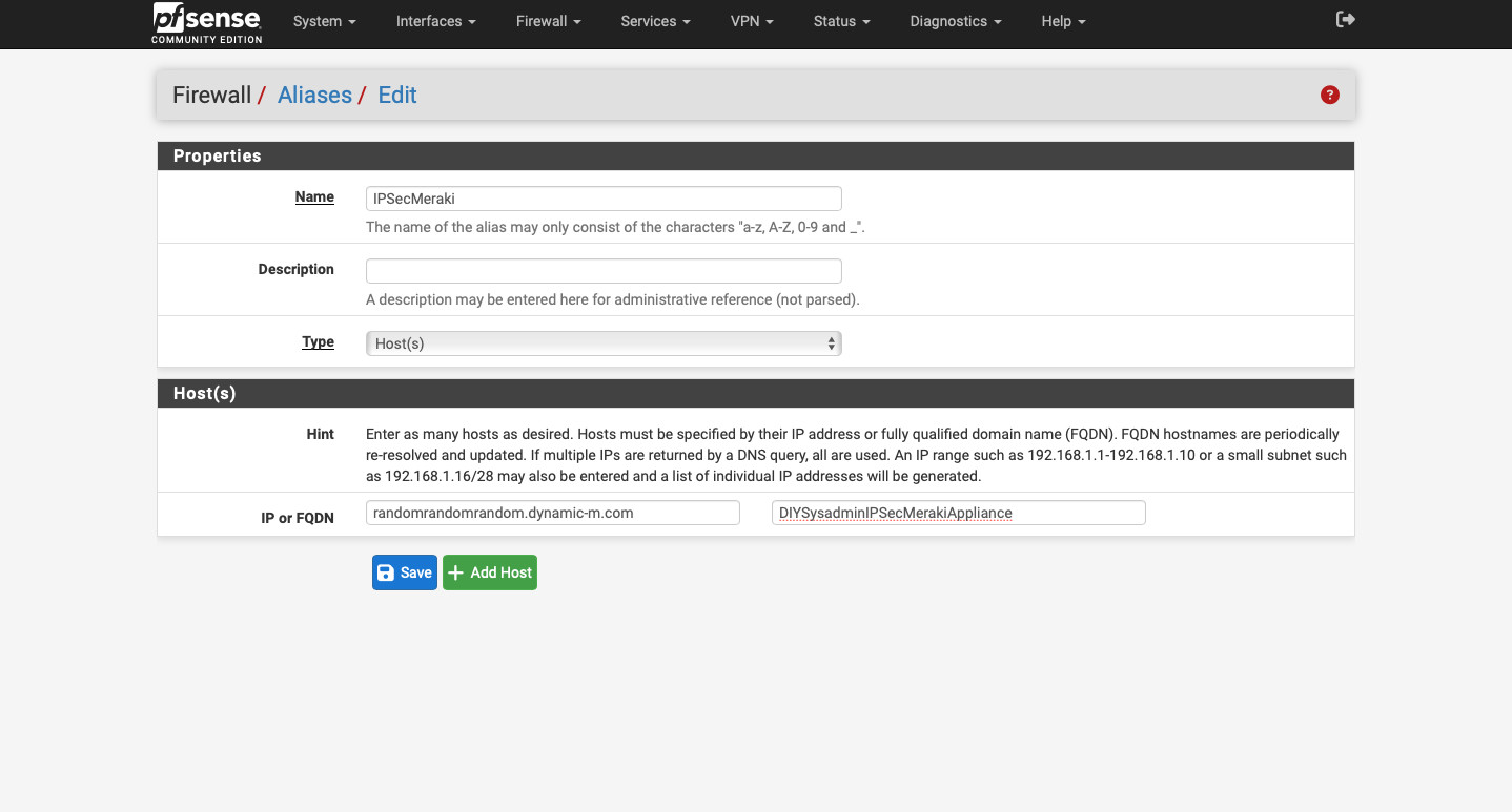
But our VPN tunnel will not be established, because we disable all auto-added VPN rules. So let’s change that. Go to Firewall -> Aliases -> IP and click the green “+ Add” button. Here we’ll create an alias for our Meraki device. Aliases in pfSense act sort of like groups. We can put multiple items into an alias and then create a firewall rule using it. If we need to make any changes, we can edit alias and those changes will propagate into the firewall rules. For this alias:
- Create a name following the requirements. We will use this name when we create our firewall rules.
- Enter a description.
- For “Type” select “Host(s)”.
- For “IP or FQDN” enter the fully qualified domain name for the Meraki appliance that we copied from Appliance status page from the Meraki Dashboard.
- Type in a description that will make sense to you if you need to figure out what you did six months down the road.
- Click the blue “Save” button.
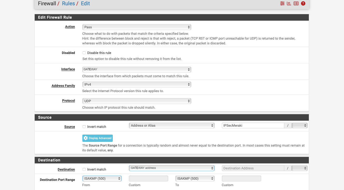
Now, go to Firewall -> Rules -> GATEWAY (or whatever your internet connected interface is called). There create 2 rules: one for ISAKMP and another for NAT-T. The screenshots are below, but:
- Select “Action” “Pass”.
- For “Interface” select “GATEWAY” (your internet connected interface).
- “Address Family” “IPv4”.
- “Protocol” “UDP” (as IPsec uses UDP for ISAKMP and NAT-T).
- Select “Address or Alias” under “Source”. Start typing the alias name we created and it should auto-populate with the name.
- In the “Destination” select “GATEWAY address”, where “GATEWAY” is your internet connected interface.
- Click the blue “Display Advanced” button in the “Destination” section.
- Select “ISAKMP (500)” for both “From” and “To” port ranges under “Destination Port Range”
- Enter a description and click “Save”.
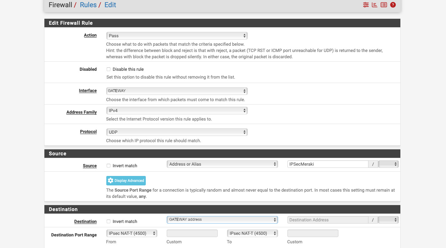
- Repeat, but select “IPsec NAT-T (4500)” for the “Destination Port Range” to create a rule allowing NAT-T.
- Save and click “Apply Changes”.
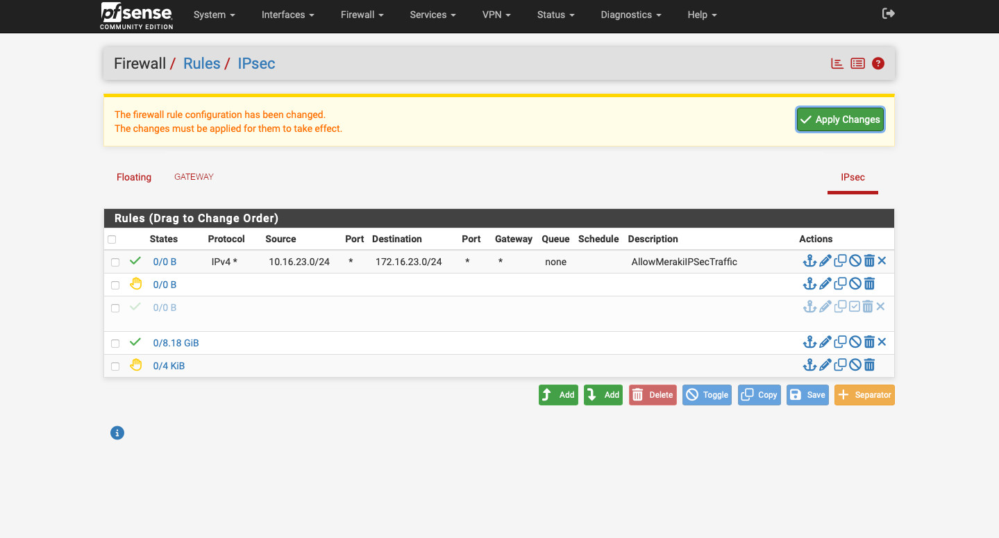
Alright. Our tunnel should form now. But no traffic will flow through. It is because, unlike Meraki, pfSense denies the IPsec tunnel traffic by default. Let’s create rule allowing in. Go to Firewall -> Rules -> IPsec and create a new rule as follows:
- “Action” – “Pass”.
- “Interface” – “IPsec”.
- “Address Family” – “IPv4”.
- “Protocol” – “Any”.
- “Source” – Meraki IP subnet, in our example it is “10.16.23.0/24”.
- “Destination” – the subnet on pfSense that we’re setting up tunnel for, in this example “172.16.23.0/24”.
- Enter the description, save, and apply changes.
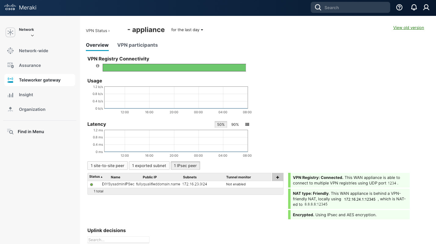
Now we should be good. On pfSense go to Status -> IPsec to confirm that the tunnel is up and running. To do the same in the Meraki Dashboard, go to Security Appliance (Teleworker gateway) -> VPN Status -> 1 IPsec peer. It should have a green circle next to the tunnel name.
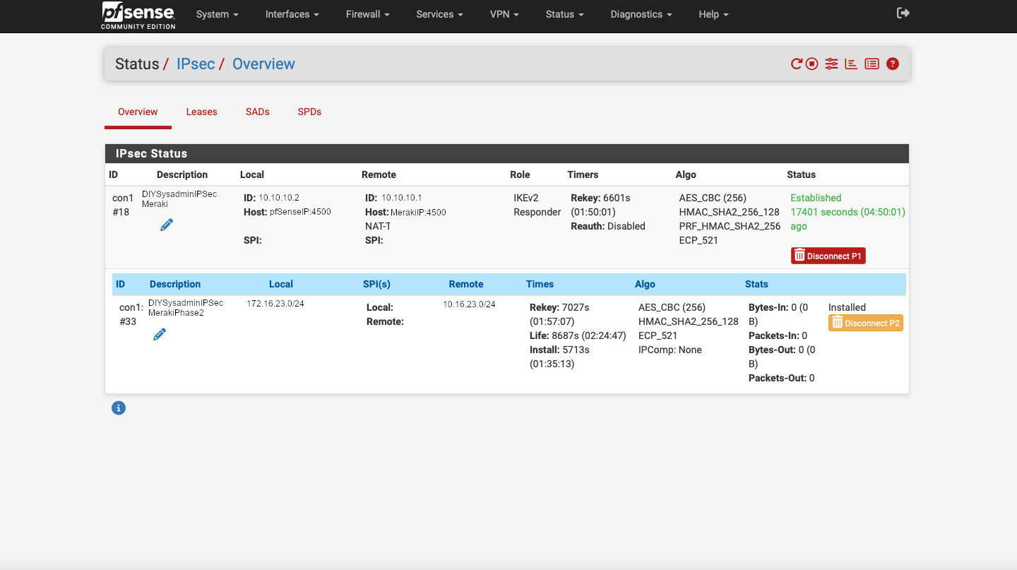
This is it. Not too complicated. Just need to make sure that the parameter match between the peers, that proper IP subnets are advertised, and that the firewall rules allow communication. If the tunnel is not being established, take packet captures on the WAN interfaces of the Meraki and the pfSense appliances. Look for unidirectional traffic and troubleshoot from there. But that is a different post…