One of the vendors that I’ve seen in small and medium businesses was Sophos. So, we can conclude that Sophos is Enterprise. Lucky for us, we can run the Sophos Firewall at home, thanks to their Sophos Home Edition Firewall. “Enterprise. At home”, remember? It is the same firewall you’d get from Sophos but with a few limitations1:
- CPU is limited to 4 cores.
- RAM is limited 6 GB.
The machine can have more resources than that but Sophos will use up to that limit. I think it’s fair enough. I’ll be virtualizing our Sophos Home Edition Firewall and will provide the resources it needs. Note, the installer requires 4 GB of RAM minimum and 32 GB of disk. It complains otherwise. Also, by default, Sophos’s Port 1 is LAN and Port 2 is WAN. Your first vNIC will be LAN and your second vNIC will be WAN. Keep this in mind when you connect your topology. By default, Port 1 is running a DHCP server with 172.16.16.0/24 subnet, and the default address for the firewall configuration is 172.16.16.16:4444.
Here’s the topology I’m using for this demonstration.
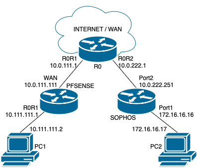
- All subnets are /24 for simplicity, unless noted otherwise.
- R0 is a pfSense instance that simulates WAN. It is connected to the internet. It runs DHCP servers for the downstream routers. The subnets are 10.0.111.0/24 on the left and 10.0.222.0/24 on the right.
- PFSENSE and SOPHOS are the firewalls/routers that we’ll be connecting via site-to-site IPsec tunnel.
- PC1 and PC2 are our end devices. We’ll use PC1 to manage PFSENSE and PC2 to manage SOPHOS.
Sophos
I’m not going to bore you with the initial Sophos setup. I am confident that you can run through the wizard.
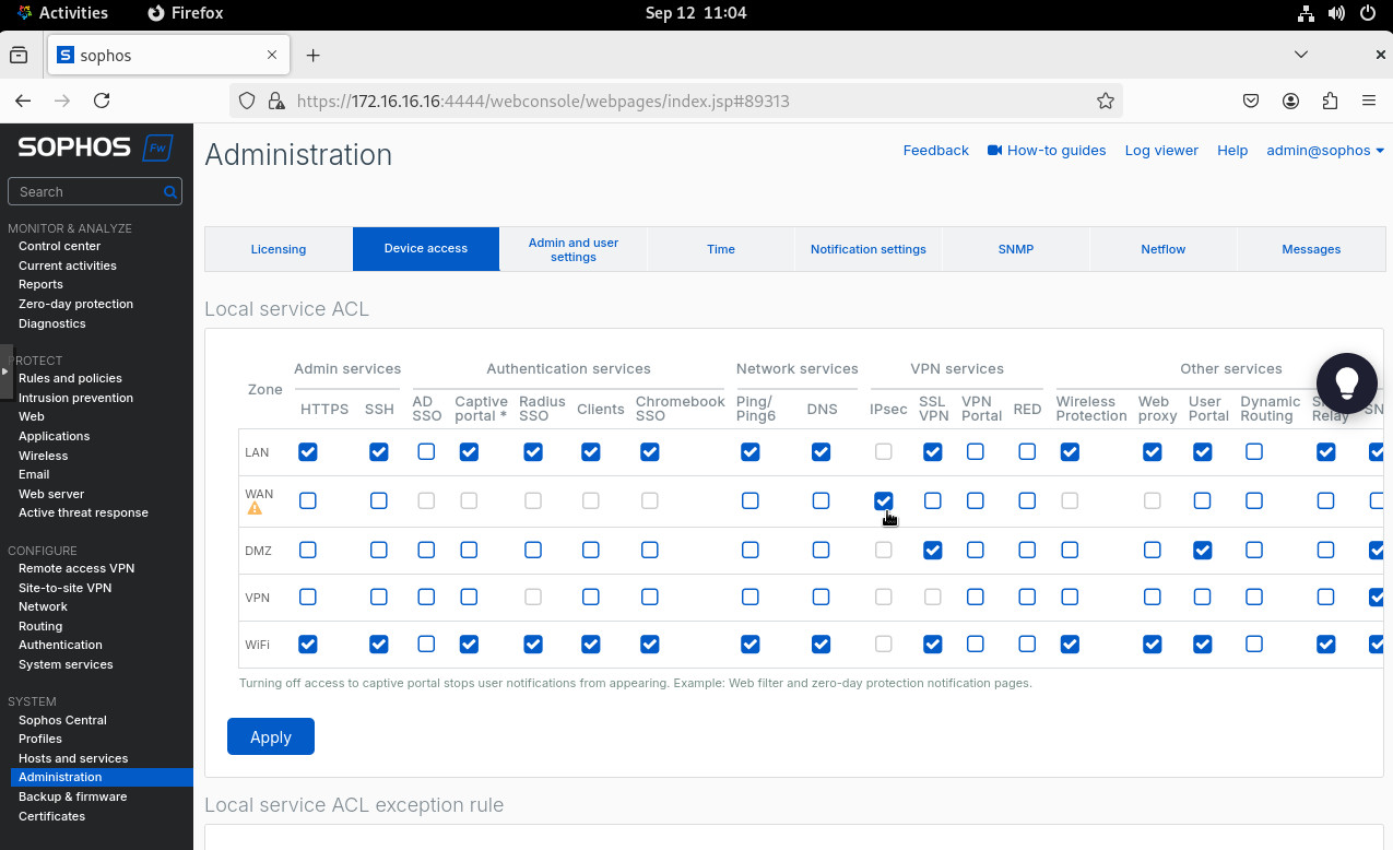
Sophos is a Zone based firewall. It is pretty intuitive and user-friendly but I did encounter a couple of “gotchas” setting IPsec up. And the first one is that we need to enable IPsec access on the WAN zone. On the right hand side pane, click on “Administration” under the “System” heading. Then go to “Device access”, check the IPSec for WAN zone and click “Apply”.
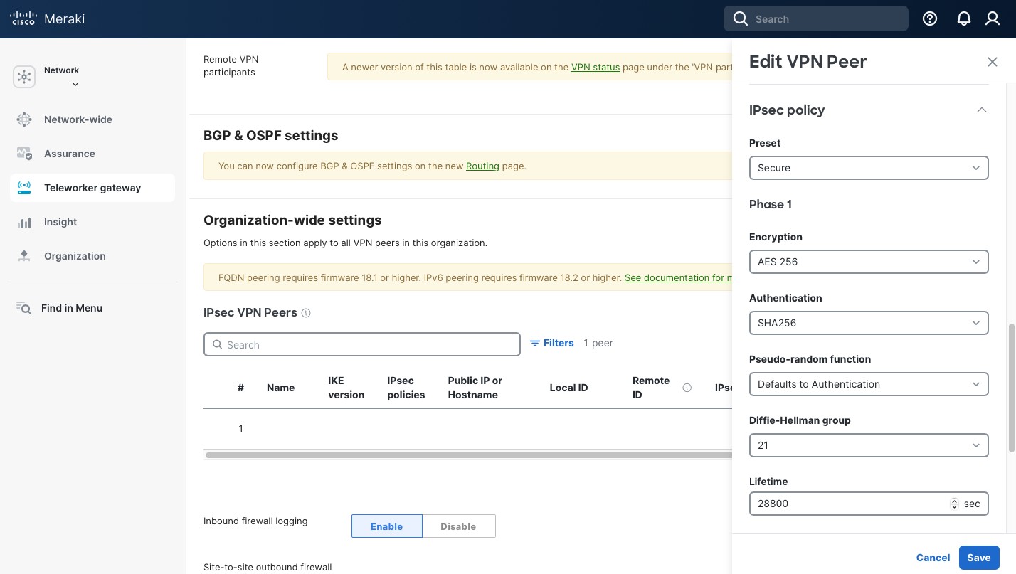
Another gotcha is that there seems to be some “miscommunication” between pfSense and Sophos when they negotiate IPsec Phase 1. If pfSense has pretty restrictive settings (I use the same settings as in my Meraki example) and Sophos has multiple settings (even if there would be a matching combination) and if Sophos is the initiator, pfSense and Sophos cannot agree on the communication parameters and can’t establish a tunnel. If pfSense is the initiator, the tunnel is established. But to work around it, I’d recommend creating an IPsec profile that matches the pfSense parameters exactly. This way there’s no “miscommunication”.
Go to “Profiles” under “System” on the right. Then to “IPsec profiles” and click “Add”.
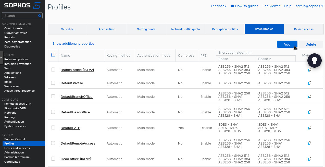
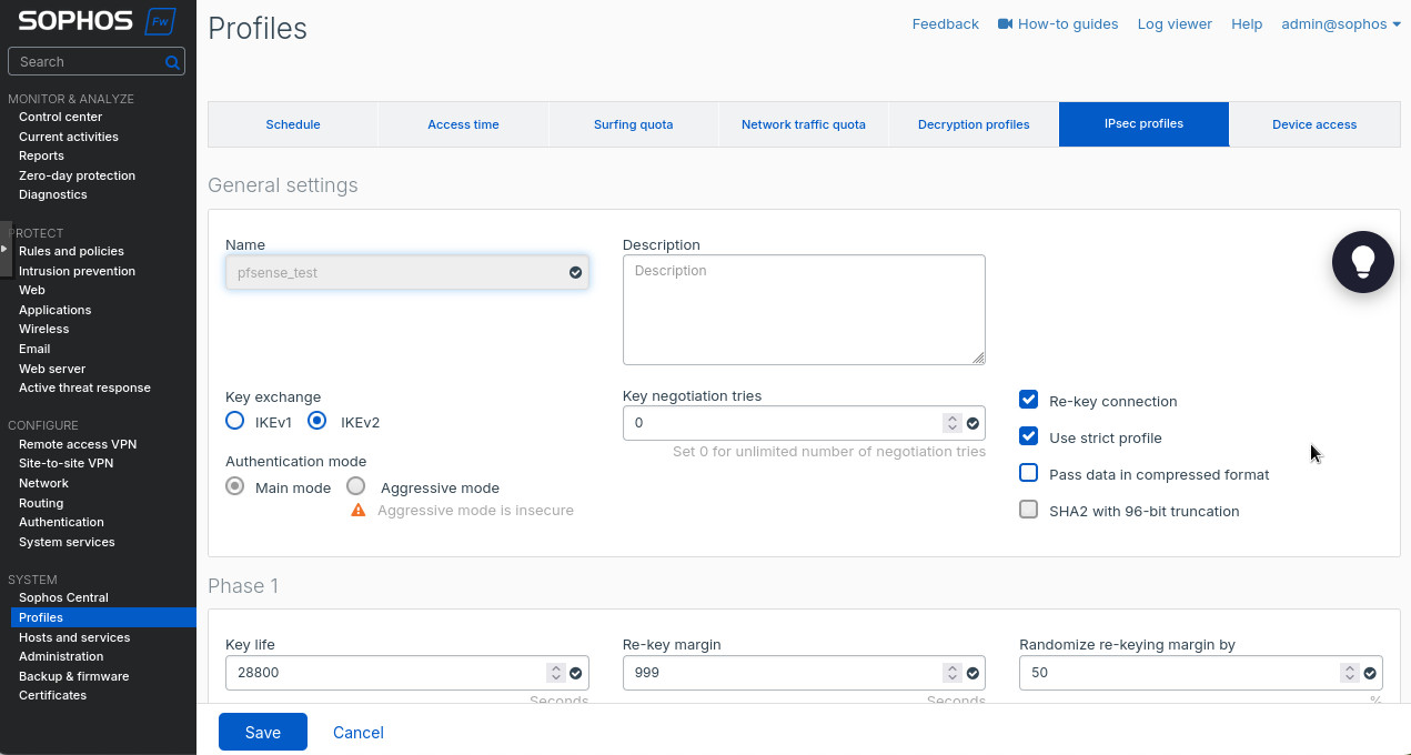
There create a new IPsec profile. I used the following settings:
- “Name”: “pfsense_test”.
- “Key exchange”: “IKEv2”.
- “Authentication mode”: “Main mode”.
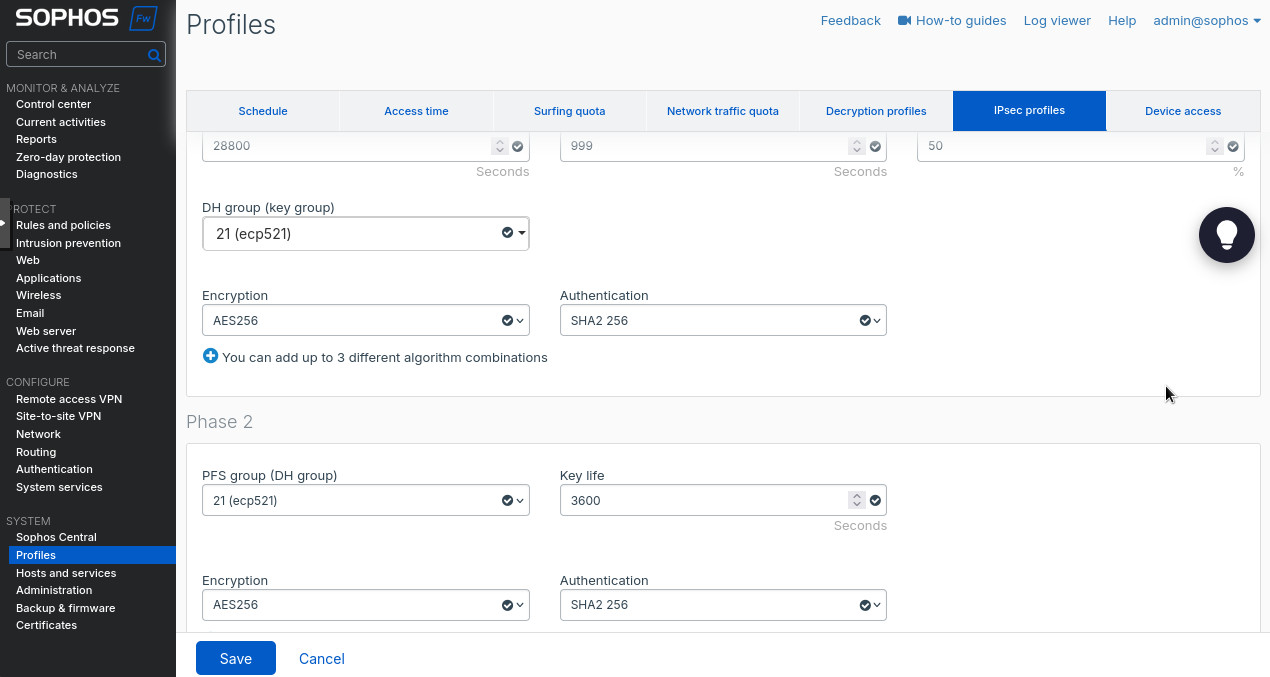
- Phase 1 “Key life”: “28800:
- Phase 1 “DH group (key group)”: “21 (ecp521)”.
- Phase 1 “Encryption”: “AES256”.
- Phase 1 “Authentication”: “SHA2 256”.
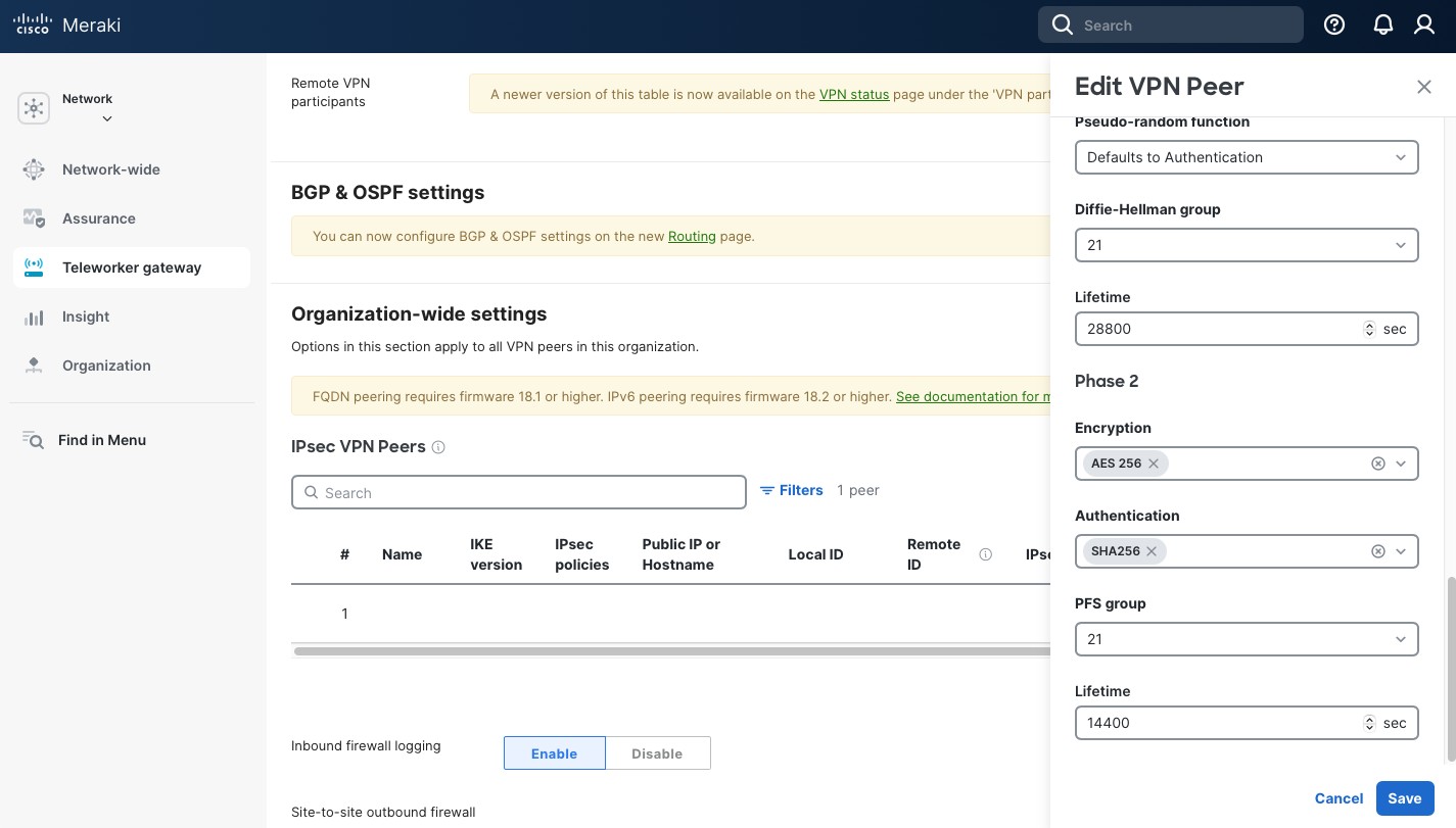
- Phase 2 “DH group (key group)”: “21 (ecp521)”.
- Phase 2 “Key life”: “3600”.
- Phase 2 “Encryption”: “AES256”.
- Phase 2 “Authentication”: “SHA2 256”.
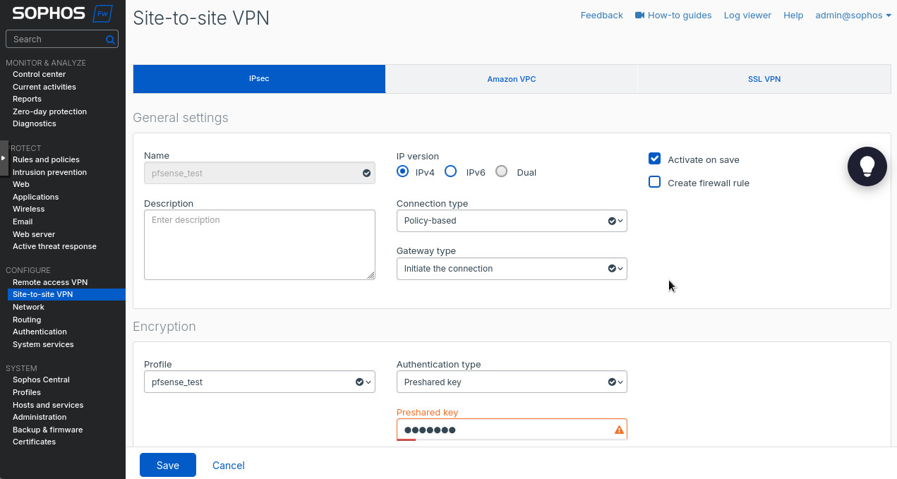
Now let’s go to “Site-to-site VPN” under the “Configure” section on the left and create a new IPsec tunnel. I used the following settings:
- “Name”: “pfsense_test”.
- “IP version”: “IPv4”.
- “Connection type”: “Policy-based”.
- “Profile” under “Encryption”: “pfsense_test”. This is the profile we created in the steps above.
- “Authentication type”: “Preshared key”.
- “Preshared key”: your super secret password.
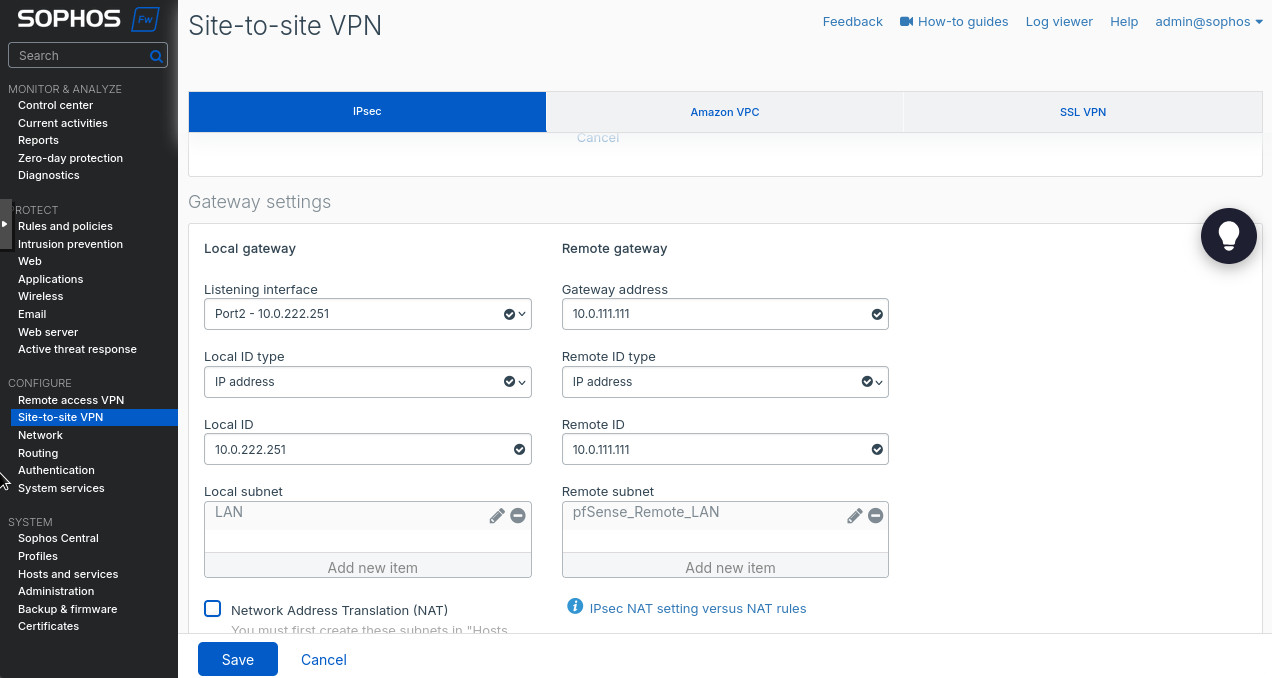
- “Local gateway” is the section where we configure the local side of the VPN tunnel. “Listening interface”: “Port 2 – 10.0.222.251”. This is your WAN interface on Sophos with its “public” WAN IP. Since we’re using it in a lab the IP in 10.0.222.0/24 range, R0’s R0R2 interface on the right side of the topology.
- “Local ID type”: “IP address” and “Local ID”: “10.222.251”. This can be arbitrary but we’ll use these settings to identify the IPsec peers, so make it make sense to you. I just use the WAN IP address.
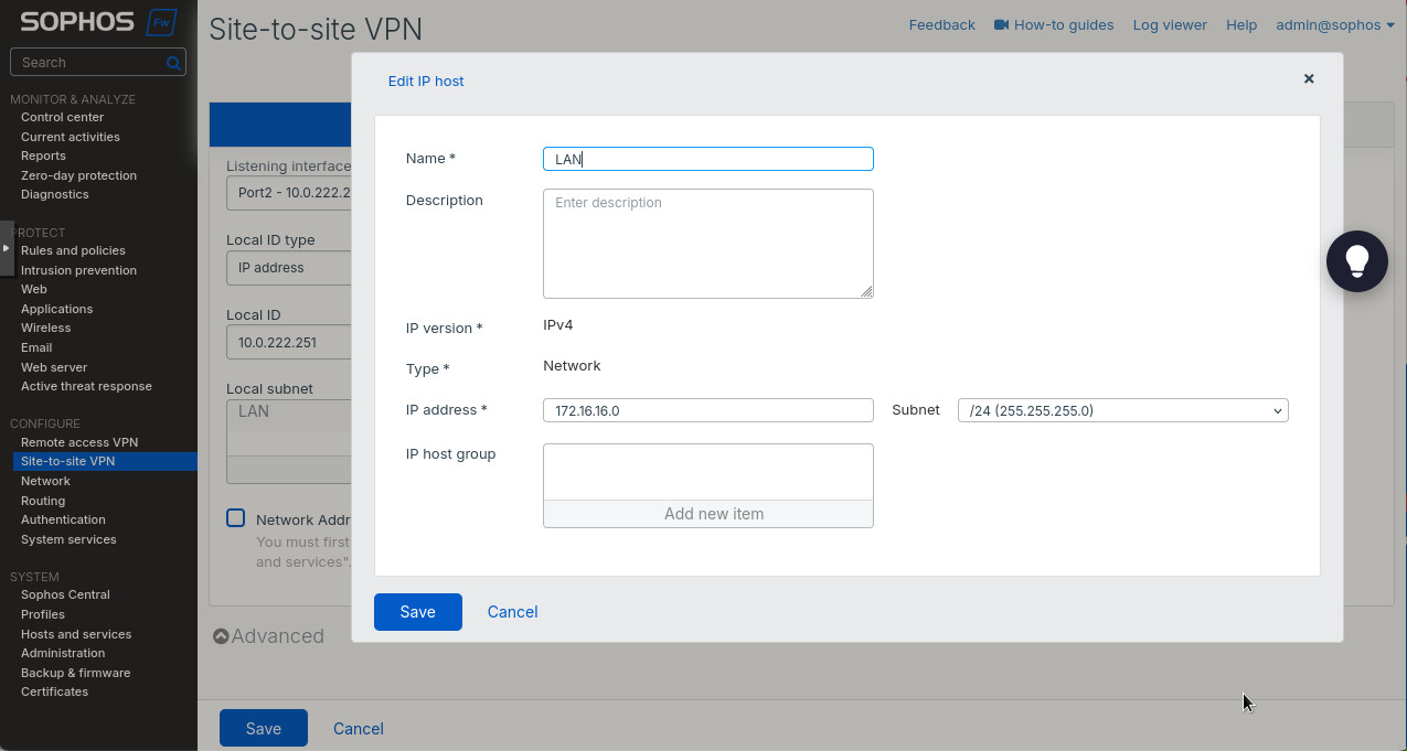
- “Local subnet”: create a new subnet as in Figure 8. We’ll be advertising the local 172.16.16.0/24 subnet to the remote peer. But you can create as many entries there as needed.
- “Remote gateway” is the pfSense side of the tunnel. In the “Gateway address” we put the public IP address of the pfSense (FQDN works too), in our case it’s 10.0.111.111. Again, refer to the topology above.
- “Remote ID type”: “IP address”.
- “Remote ID”: “10.0.111.111”.
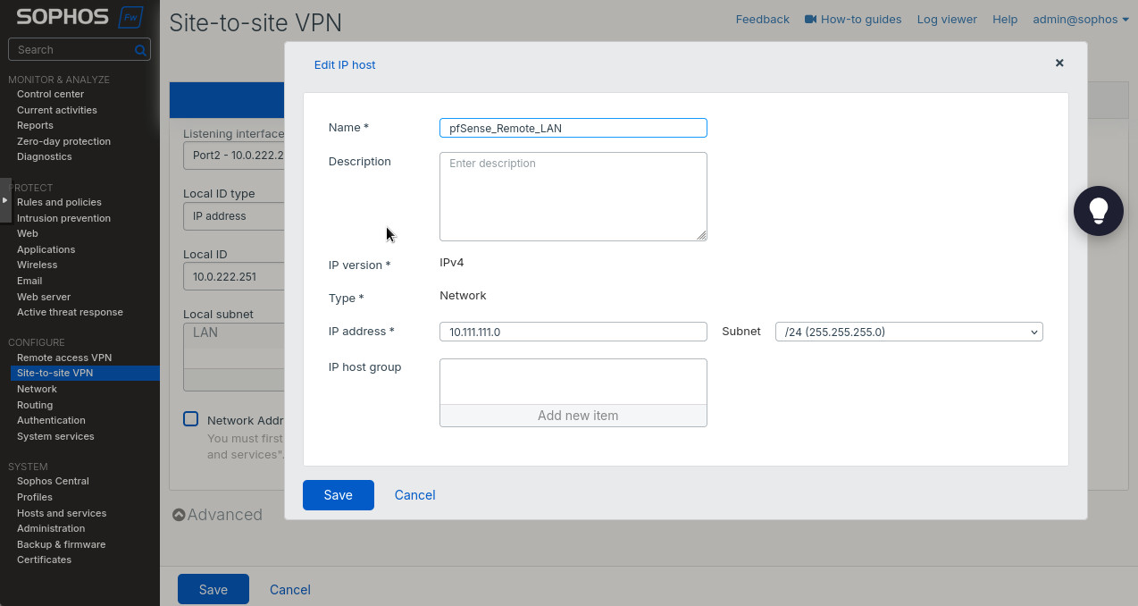
- Create a “Remote subnet” as in Figure 9. The subnet we use is 10.111.111.0/24, the LAN subnet off pfSense’s R0R1 interface.
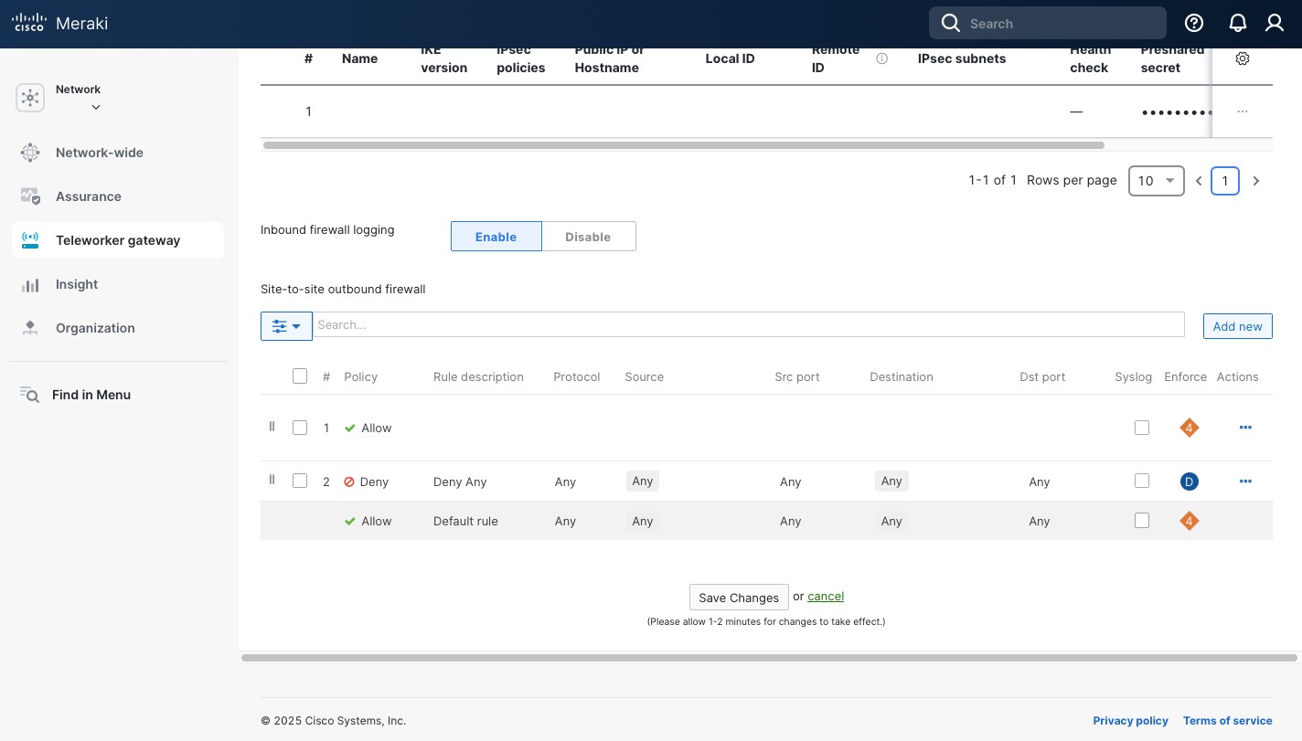
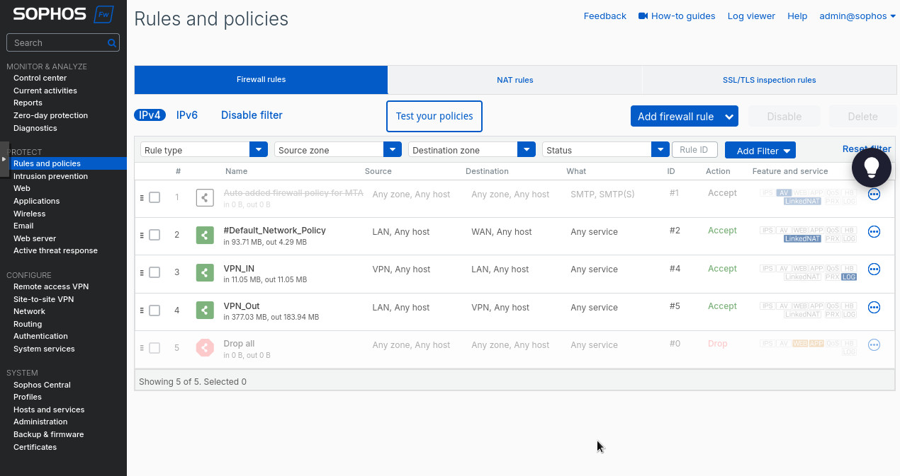
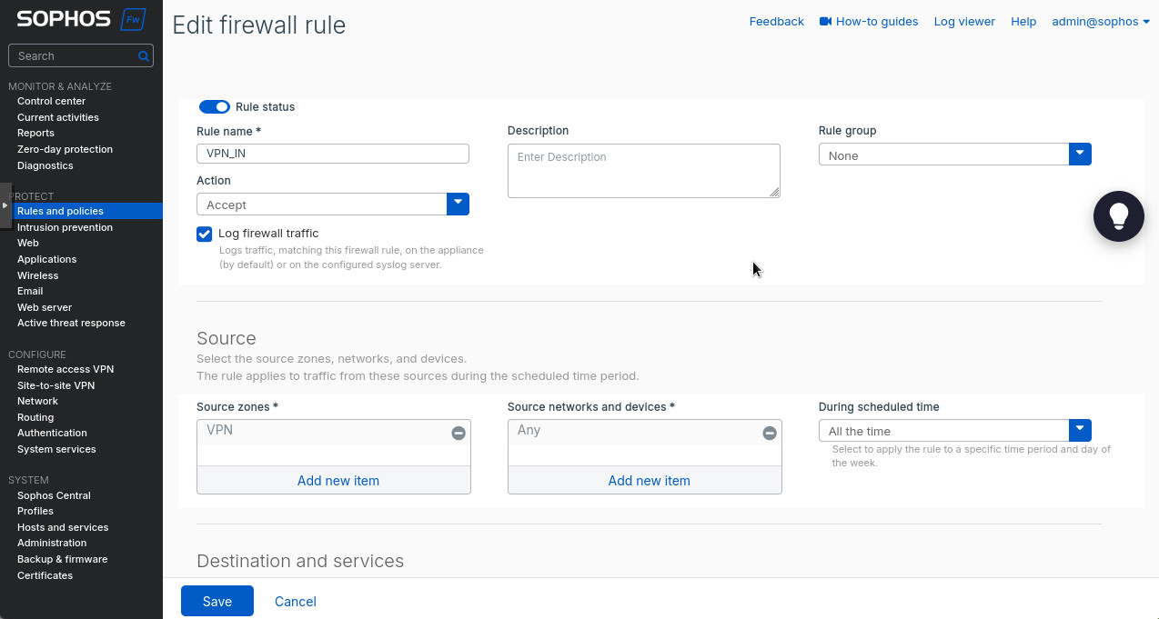
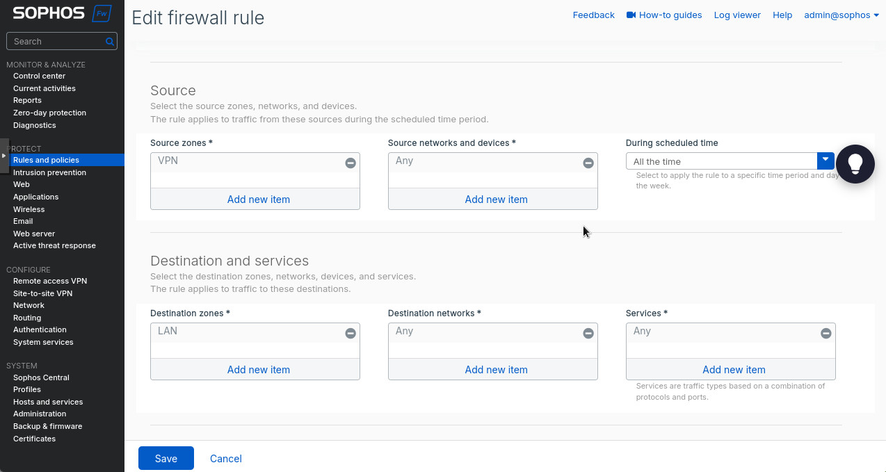
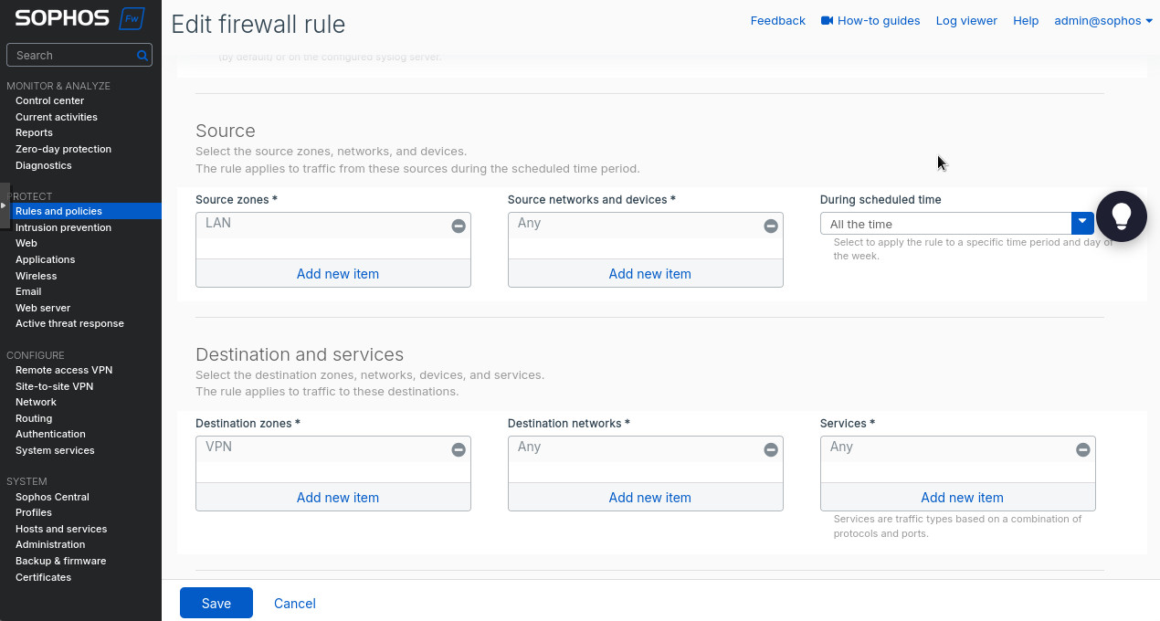
After saving, we can enable and activate our tunnel. Did you think we were done? No way! We need to create the firewall rules to allow the traffic between the subnets across the tunnel. Head to “Rules and policies” under the “Protect” section. There we’ll create 2 firewall rules: allowing LAN to VPN and allowing VPN to LAN. Essentially, you’ll select “VPN” as the source zone and “LAN” as destination to allow traffic from the VPN tunnel to the LAN. Make sure to select “Accept” as the “Action”. Switch “LAN” and “VPN” around to allow LAN traffic through the tunnel.
OK. We’re done with Sophos. I promise. But we’re only half way done with the tunnel. Time to configure the pfSense side.
pfSense
The pfSense configuration will be very similar to what we did when we setup a tunnel with Meraki. So I may omit some details.
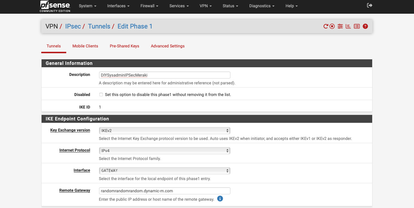
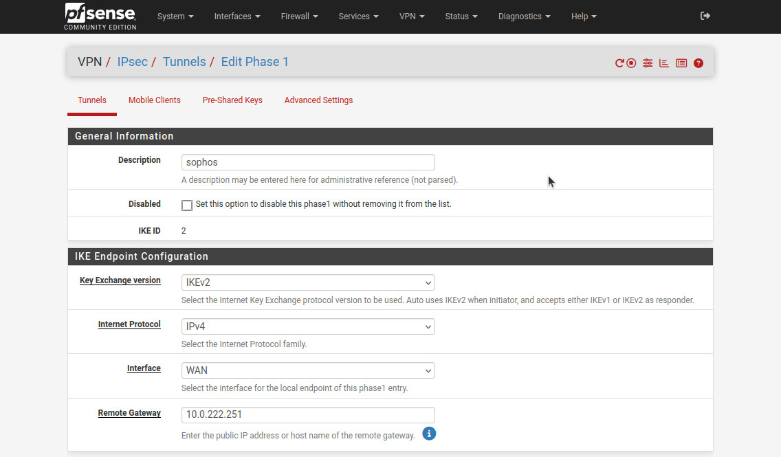
As always we start with creating Phase 1 and Phase 2 settings for the IPsec tunnel. Head to VPN -> IPsec. Here are the settings I used:
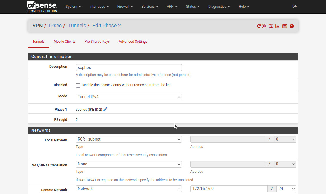
- “Description”: “sophos”.
- “Key Exchange version”: “IKEv2”.
- “Internet Protocol”: “IPv4”.
- “Interface”: “WAN”. This is the interface that is connected to “internet”.
- “Remote Gateway”: “10.0.222.251”, the “public” IP address of Sophos. FQDN also works.
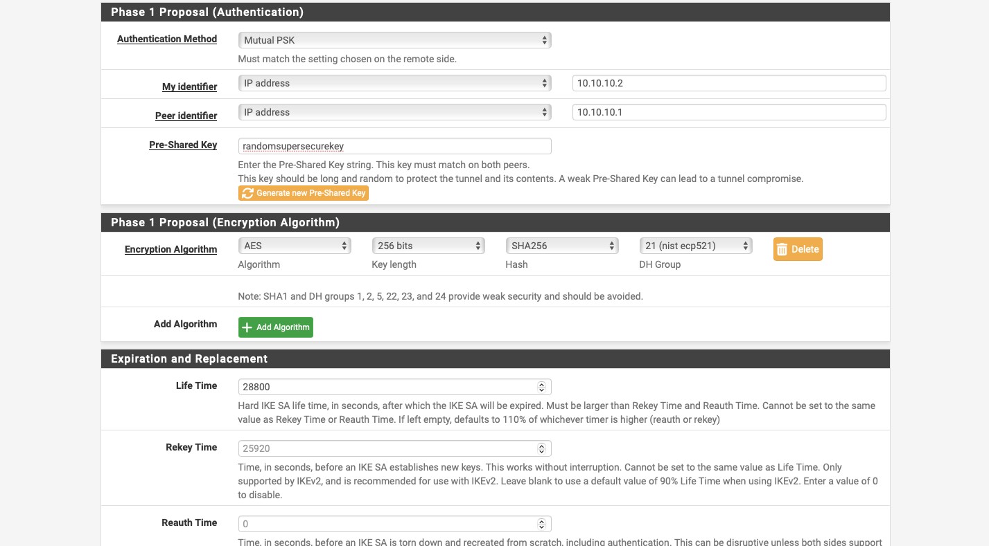
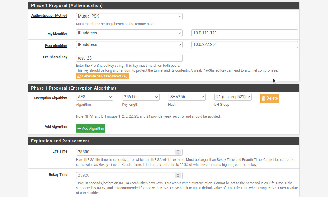
- For “Phase 1 Proposal (Authentication)”, “Authentication Method”: “Mutual PSK”.
- “My Identifier”: “IP address” and “10.0.111.111”. Make sure this matches the “Remote ID” set up in the Sophos IPsec configuration.
- “Peer Identifier”: “IP address” and “10.0.222.251”. Make sure this matches the “Local ID” set up in the Sophos IPsec configuration.
- “Pre-Shared Key”: use your super secret password that you put into the Sophos configuration. Do NOT use “test123”, it’s bad!
- For “Phase 1 Proposal (Encryption Algorithm)”, “Encryption Algorithm”: “AES” for “Algorithm”, “256 bits” for “Key length”, “SHA256” for “Hash”, and “21 (nist eco 521)” for “DH Group”.
- Put “Life Time”: “28800”.
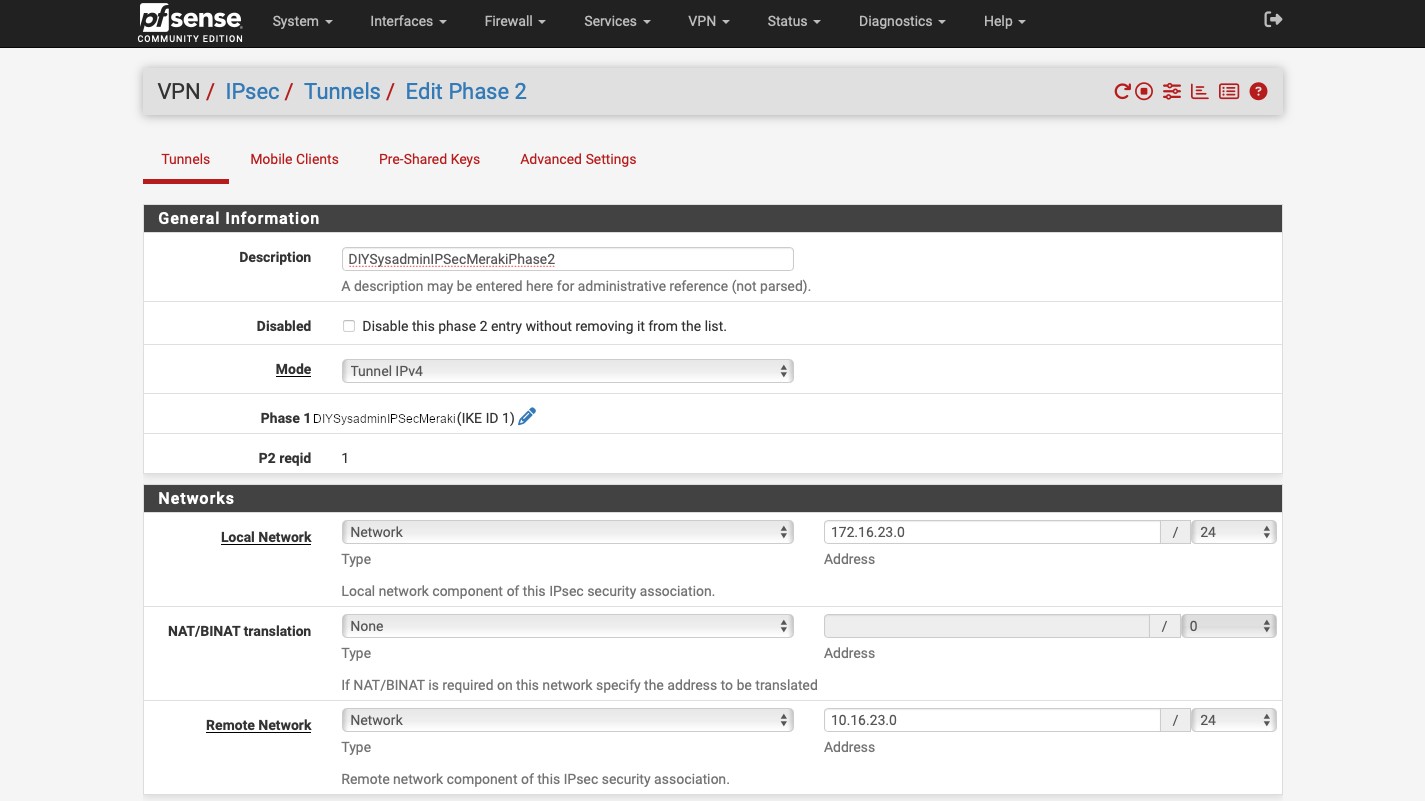
For Phase 2, I used the following settings:
- “Description”: “sophos”.
- “Mode”: “Tunnel IPv4”.
- “Local Network”: “R0R1 subnet”. Make sure that the subnet on the pfSense is the same as configured in the Sophos configuration for “Remote subnet”.
- “Remote network”: “172.16.16.0/24”, the same network as “Local subnet” in the Sophos IPsec configuration.
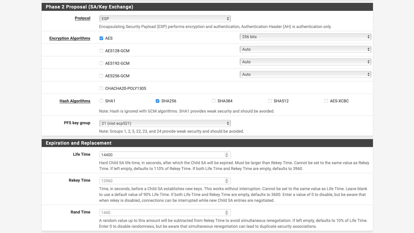
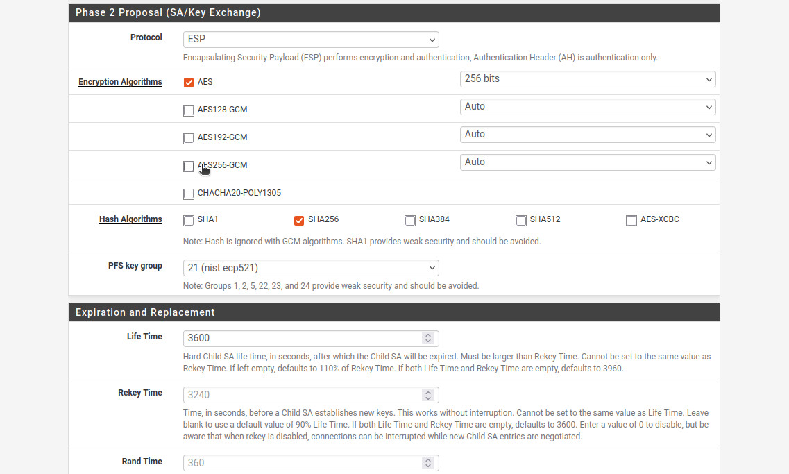
- For the “Phase 2 Proposal (SA/Key Exchange)”: “Protocol”: “ESP”. This will ensure that the traffic is encrypted.
- “Encryption Algorithms”: “AES”, “256 bits”.
- “Hash Algorithms”: “SHA256”.
- “PFS key group”: “21 (nist ecp521)”.
- “Life Time”: “3600”.
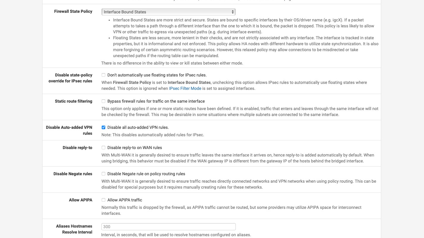
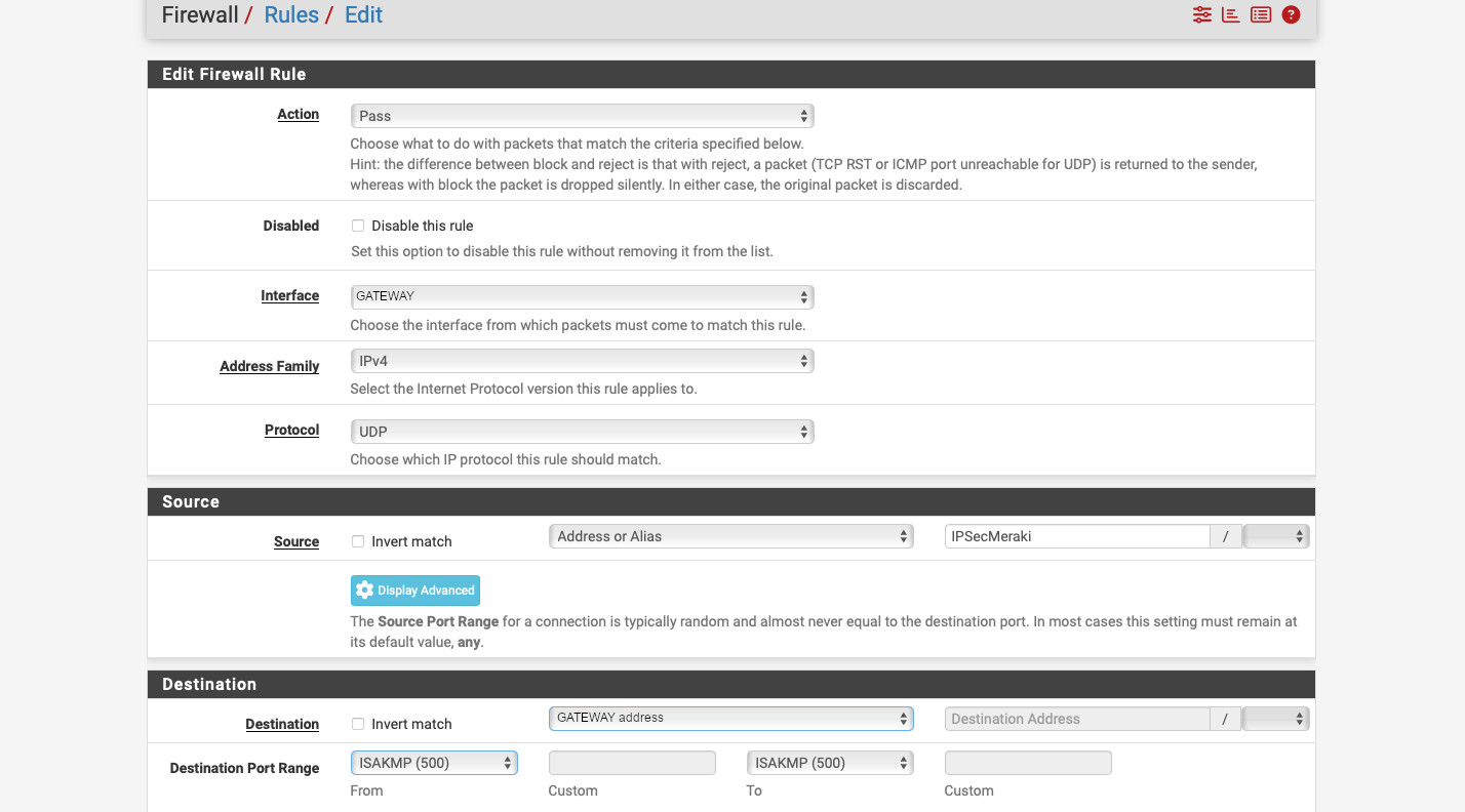
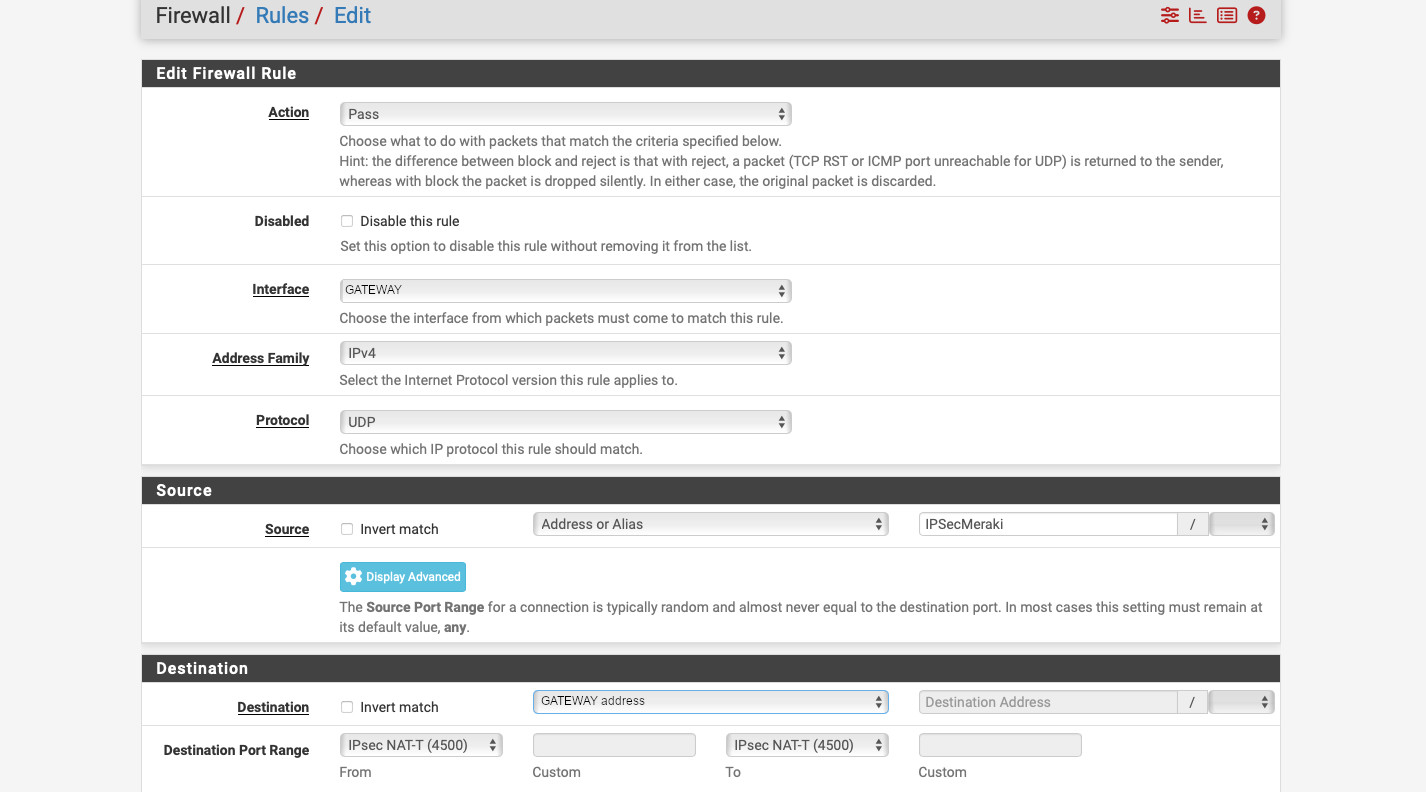
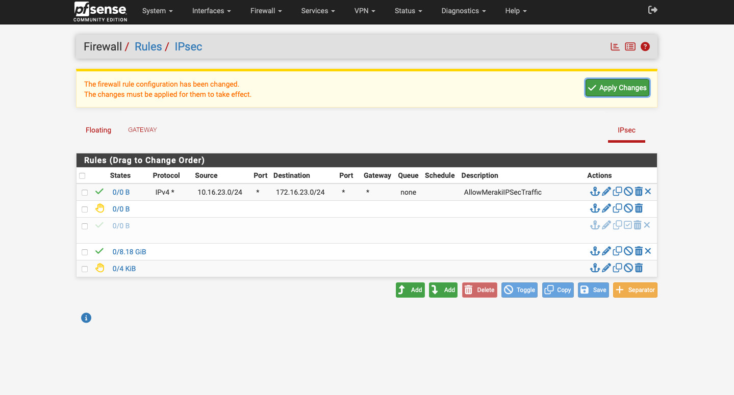
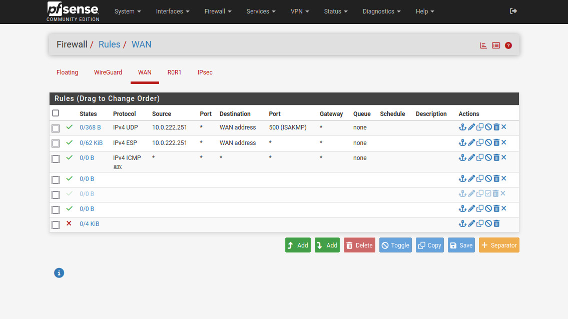
Now, we need to configure the inbound firewall rules. Head to Firewall -> Rules -> WAN. Create two rules: one allowing UDP from “10.0.222.251” (Sophos “public” IP) to “WAN address”, port “500 (ISAKMP)”, and one for ESP from “10.0.222.251” to “WAN address”. If you’re behind a NAT, then you’ll need to create a rule allowing UDP port 4500 (NAT-T). Make sure you create appropriate rules to allow traffic between the subnets behind the VPN. The interface group is called “IPsec” in the Firewall -> Rules section.
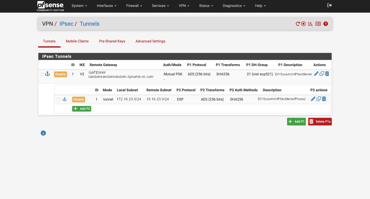
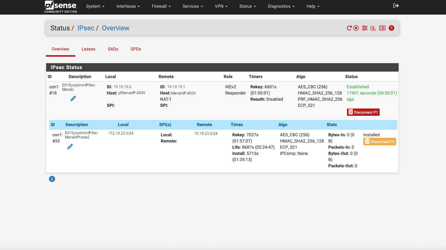
After all of that we can see that our tunnel is established. Head to Status -> IPsec to confirm.
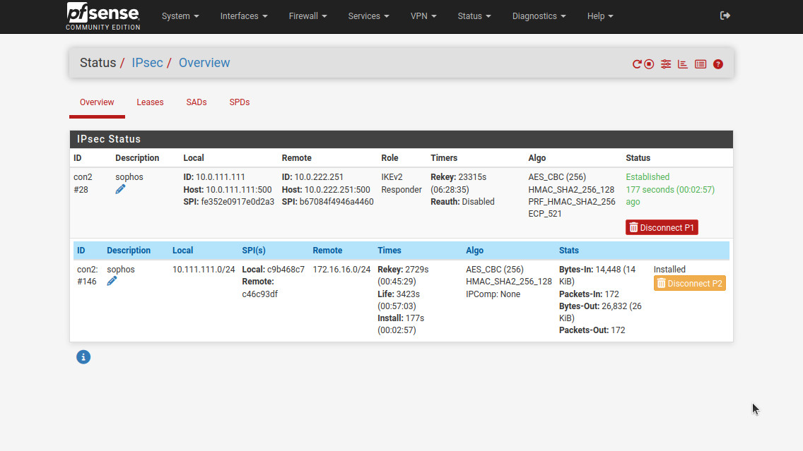
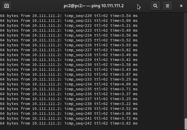
We can also confirm that the tunnel allows traffic by pinging from PC1 to PC2 and vice-versa.
And this is it. Just like with the Meraki security appliance, the set up is simple just tedious. There were a couple of gotchas: allow VPN access on WAN and create an IPsec profile. But that’s the price of running enterprise at home…